Flowchart
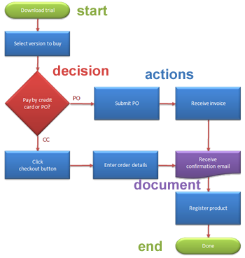 A flowchart is a diagram that represents an algorithm or process. It can give a step-by-step solution to a problem that is easy to follow.
The flowchart shows the 'process operations' (what you have to 'do') within different shaped 'boxes', and indicates step-order by connecting the the box outlines with arrowed lines - connecting them to show the flow of control.
Flowcharts are used in analyzing, designing, documenting or managing a process or program in various fields.
It is important to connect these steps in a logical in order. All processes should flow from top to bottom and left to right.
Symbols
A typical flowchart has the following kinds of symbols:
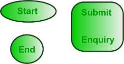
| Start and end symbols |
Represented as circles, ovals or rounded rectangles, usually containing the word "Start" or "End", or another phrase signaling the start or end of a process, such as "submit enquiry" or "receive product". |
|
| Arrowed lines |
Showing "flow of control" (the order you need to go through the process). An arrow coming from one symbol and ending at another symbol represents that control passes to the symbol the arrow points to. |
|
| Actions |
Generic processing steps are represented as rectangles - tell you what to do. Example: "Add 1 to A"; |
|
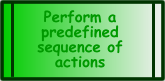
| Subroutines |
Represented as rectangles with double-struck vertical edges; these are used to set in motion a predefined action sequence that may be detailed in a separate flowchart. |
|
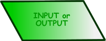
| Input/Output |
Represented as a parallelogram. Example: Get X from the user (input) or display X (output). |
|
| Preparation for a later stage |
Represented as a hexagon. Shows operations which have no effect other than preparing a value for a subsequent conditional or decision step. |
|
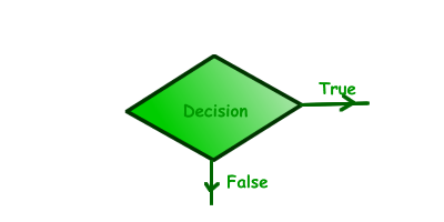
| Conditional or decision |
Represented as a diamond (rhombus). Occurs where a decision is necessary - commonly a Yes/No question or True/False test.
The conditional symbol is peculiar in that it has two arrows coming out of it, usually from the bottom point and right point, one corresponding to Yes or True, and one corresponding to No or False. (The arrows should always be labeled.)
More than two arrows can be used, but this is normally a clear indicator that a complex decision is being taken, in which case it may need to be broken-down further or replaced with the "pre-defined process" symbol. |
|
| Junction symbol |
Generally represented with a black blob (in the same way as circuit junctions are represented in circuit diagrams). They indicate where multiple control flows converge to form a single exit flow.
A junction symbol will have more than one arrow going into it, but only one going out.
In simple cases, one may simply have an arrow point to another arrow instead. These are useful to represent loops. For additional clarity, wherever two lines accidentally cross in the drawing, one of them may be drawn with a small semicircle over the other, showing that no junction is intended. |


|
| Labelled connectors |
These are junctions represented by an identifying label inside a circle instead of a 'blob'. Labelled connectors are used in complex or multi-sheet diagrams to substitute for arrows.
For each label, the "outflow" connector must always be unique, but there may be any number of "inflow" connectors. In this case, a junction in control flow is implied. |
|
| Parallel mode |
Concurrency (running at the same time) is represented by a double transverse line with any number of entry and exit arrows. These symbols are used whenever two or more control flows must operate simultaneously. The exit flows are activated concurrently when all of the entry flows have reached the concurrency symbol. A concurrency symbol with a single entry flow is a fork; one with a single exit flow is a join. |
|
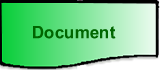
| Document |
Represented by a rectangle with a wavy base; |
|
| Manual input |
Represented by quadrilateral, with the top irregularly sloping up from left to right. An example of its use would be to signify data-entry from a form; |
|
| Manual operation |
Represented by a trapezoid with the longest parallel side at the top. This is used to represent an operation or adjustment to process that can only be made manually. |
 |
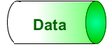
| Data File |
Represented by a cylinder - full cylinder is direct data input.
Open at one end means stored data |
 |
-
-
-

A well constructed flowchart makes it easy for someone to follow a procedure.
-
- A computer program is a procedure that a machine has to follow. The algorithm needs to be planned in a flowchart so that the flow of the program can be carefully assessed before programming begins. A flowchart is part of the early design stage in programming.
-